
How a Moment of Inertia Calculator Helps Optimize Structural Sections
Jun 29, 2026 | By Team SR
A beam or column section gets chosen long before any analysis model exists. During basic design, the engineer locks in approximate profile sizes, and the accuracy of those decisions sits around 20-30%. The section fixed at this point drives both the weight of the structure and whether it passes code checks later. One of the most influential properties governs that choice: the moment of inertia of the section. The sections below cover why the moment of inertia controls both stiffness and stability, how sizing a beam differs from sizing a column, and where manual property calculation breaks down.
 Follow us
 Follow us
The Moment of Inertia Decides Which Section Passes
Beam deflection is inversely proportional to the moment of inertia. For a simply supported beam under uniform load, δ = 5wL⁴/(384EI), so doubling I cuts deflection in half. The Euler critical load behaves just as directly: Pcr = π²EI/(KL)², where doubling I doubles the load at which a column buckles.
I appears in both checks that most often govern a section early on: deflection (serviceability limit state) and buckling (ultimate limit state).
One distinction saves trouble downstream. The moment of inertia describes stiffness, while bending strength comes from the section modulus S = I/c, where c is the distance to the extreme fiber. Two sections with the same I can have different S if c differs. Deflection and buckling depend on I. Bending stress σ = M/S depends on S. The two properties cannot be used interchangeably when sizing a member.
RECOMMENDED FOR YOU


Section Optimization Starts with Geometry
The moment of inertia is defined as I = ∫y²dA. Every area element counts toward the sum, weighted by the square of its distance from the neutral axis. The practical consequence is simple: material near the neutral axis adds almost no stiffness, while the same material pushed to the edge raises I sharply. The parallel-axis theorem, I = I_c + Ad², shows why: the Ad² term grows with the square of the distance from the axis.
The canonical example: three identical boards stacked flat in a sandwich, versus the same three boards arranged as an I-beam with the flanges spread apart. The I-beam comes out 3.6 times stiffer at the same mass, and the entire gain comes from the Ad² term.
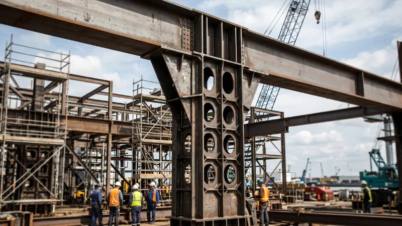
The same principle drives industrial profiles. Cellular beams raise web depth by roughly 50% without adding steel, and for a given span, come out lighter than solid beams. Section optimization, in the end, is a question of how material is distributed: shaping the geometry buys stiffness more cheaply than adding mass.
Beams and Columns Optimize Against Different Criteria
Carrying beam intuition over to columns is an easy way to go wrong. For a beam, the sizing criterion reduces to maximum I: it governs both deflection and lateral-torsional buckling. For a column, the criterion shifts to the radius of gyration, r = √(I/A). The Euler critical stress, σcr = π²E/(Leff/r)², depends on the slenderness Leff/r. The absolute value of I is secondary here.
Two columns with the same r buckle at the same stress, regardless of cross-sectional area. A section with a higher r therefore delivers more buckling resistance per unit weight, which makes r the right basis for ranking column candidates. Hollow profiles win over solid ones here: mass sits at the perimeter, so the radius of gyration is higher for the same area. For the compression chords of a lattice crane boom or offshore platform bracing, this criterion decides whether the member survives its axial load.
A peer-reviewed study of steel column efficiency measuring capacity-to-weight under AISC 360-16 found that at a 3 m height, an I-section was 30% less efficient than a cruciform section. At 4 to 5 m, the cruciform delivered up to 30% more capacity per unit weight than an H-section. The gap widens with column height, because slenderness amplifies the radius-of-gyration advantage.
Where Manual Property Calculation Breaks Down
For a standard rolled profile, the moment of inertia and radius of gyration come straight from tables. The trouble starts with non-standard and built-up sections: a welded plate girder, a box from plates, a profile with cutouts, and a monosymmetric section. Their properties are computed by hand, and that is where errors accumulate.
The first source of error is the parallel-axis theorem itself. It applies only from the centroidal axis of each component. The typical slip: taking a component’s own moment of inertia about an arbitrary axis, or dropping the Ad² term for an offset component. In a three-plate welded girder, the theorem gets applied three times, and an error in any one step propagates through the rest of the calculation.
Units magnify any slip. The moment of inertia carries dimensions of length to the fourth power, so confusing mm⁴ with cm⁴ throws the result off by a factor of ten thousand. Unsymmetric sections also require the product of inertia, Iyz: without it, the neutral axis of an L-section is oriented incorrectly, and the stress at the corners comes out underestimated.
Torsion is the most treacherous. For an open profile, the torsional constant J is not the same as the polar moment of inertia, and substituting the polar moment for J on an I-section overstates torsional resistance by a factor of hundreds. The warping constant Cw, which feeds the lateral-torsional buckling check, is absent from tables for a built-up section and has to be computed separately.
Section Properties in the Sizing Loop
Comparing options calls for fast iteration: a dozen candidate profiles, each with area, moment of inertia about both axes, radius of gyration, section modulus, J, and Cw. By hand, that means hours of work and an opening for the errors above. A moment of inertia calculator closes this step: from the profile dimensions, it returns A, Iy, Iz, ry, rz, the elastic and plastic section modulus, J, and Cw, including for non-standard and built-up shapes that no table covers. The engineer gets a direct comparison of candidates against the relevant criterion before any FE model is built: by I and section modulus for a beam, by radius of gyration for a column.
The same set of properties is what the codes ask for. In Eurocode 3 (EN 1993-1-1), the compression buckling check Nb, Rd = χ·A·fy/γM1 leans on the radius of gyration through the non-dimensional slenderness, and the LTB check requires Iy, Iz, J, and Cw. The section class, 1 through 4, sets whether bending is taken on the plastic or the elastic section modulus. AISC 360 organizes its column tables by radius of gyration, and ties beam strength to the plastic and elastic section modulus. Correct section properties at the input stage are the condition for passing these checks on the first run.
The same outputs show why the I-beam is efficient. The shape factor, the ratio of plastic to elastic section modulus, is 1.5 for a solid rectangle but only 1.10 to 1.18 for an I-beam. The I-beam already works close to the limit of its geometry, with little extra reserve to gain from plastification.
The Cost of Early-Stage Decisions
Rework from design errors stays an expensive line in any project budget, and much of it is seeded early. Section decisions are made exactly here, where estimates are coarsest and the leverage on the outcome is greatest.
By 2025-2026, the material argument has sharpened too. Buildings account for about 39% of global energy-related CO₂ emissions, and 11% of that comes from materials and construction, the embodied carbon of the structure. Material quantity is directly proportional to that figure. A geometrically efficient section lowers steel mass, and with it the carbon footprint and the cost. The SE 2050 initiative names structural material efficiency as one of the two main levers for cutting embodied carbon. That lever has the most reach when the section is chosen, before the model is built, and while a variant still takes minutes to recompute.
Recommended Stories for You

Team SR Nov 24, 2025


Team SR Feb 11, 2026

Team SR Jan 28, 2026

Team SR Apr 15, 2026

Trending Stories

The Role of HR in Aligning Leadership Decisions With Employee Reality

The US Engineering Credential European Deep Tech Founders Are Picking Up

Crafting Positive Momentum on TikTok via Improved Interaction Habits

iGaming License: Meaning, Importance, and Its Role in the Global Online Gaming Industry

How to Find the Best Online Reputation Management Services When Everyone Claims to Be the Best

The Best Forex Trading Platforms for Beginners in 2026

Turning Complex Challenges into Clear Opportunities

Why Hiring Readiness Matters More Than Ever for Fast-Growing Startups